Assembly Instructions
Preparing the microcontroller
The switch matrix uses an Arduino Mega 2560 Rev3 as a microcontroller. In order to use the microcontroller the proper firmware needs to be installed (flashed) onto the Arduino. This should preferably be done before inserting the microcontroller into the enclosure.
The Arduino firmware is available in the GitHub repository in the /firmware folder.
To flash the firmware you need:
- 1x Arduino Mega 2560 Rev3
- 1x Ethernet Shield 2
- 1x USB 2.0 A to USB 2.0 B cable
- A computer with the Arduino IDE configured
Setting up the Arduino IDE
The Arduino IDE can be downloaded from here. Start the IDE and perform the following steps:
- Open the
.inofirmware file (in Arduino known as a sketch) - Change Tools > Board to “Arduino Mega or Mega 2560”
- Connect the Arduino to the PC using the USB cable
- Change Tools > Port to the COM port of the Arduino
- Install Vrekrer SCPI Parser:
- Open Library Manager by going to Sketch > Include Libraries > Manage Libraries…
- Search for “Vrekrer SCPI Parser”
- Press Install
Flashing the firmware
With the Arduino IDE set up and the firmware .ino file open:
- Take note of the MAC address on the Ethernet Shield 2. If the shield is new this should be on a sticker on the underside of the shield.
- In the
.inofile, change the bytes in the linebyte mac[] = { 0xA8, 0x61, 0x0A, 0xAE, 0xAA, 0x3B };to the shields MAC address.- If the shield is missing a MAC address, it can be set to an arbitrary combination of 6 bytes, however it must be unique on the network the Ethernet shield connects to.
- Next you need to configure what type of switches the Arduino will be controlling:
- Two configurations are available per default: one for 3 SP6T switches, and one for one SP6T switch and 12 SPDT switches. You can find these configurations commented out below the MAC address. Simply un-comment whichever configuration you need.
- If you need a different configuration, you can write it yourself with the premade ones as guidelines. Keep in mind that some pins are not usable by the Arduino, as commented in the
.inofile. For adding more types of switches refer to the existing code inSwitch.cppandSwitch.h.
- Flash the code to the Arduino by pressing the Upload button. This will compile the sketch and send it to the Arduino. Assuming no errors occur, the Arduino is now ready to use.
- Sometimes the Arduino IDE can’t find the Arduino. If so, try to change the COM port in Device Manager for the Arduino USB to something else, restart the Arduino IDE and select the new COM port under Tools > Port.
- To verify that the Arduino is working: Open the Serial Monitor by pressing the button in the top right of the Arduino IDE. This window shows the serial communication with the Arduino. Now, try to Upload again. If everything works you should see the Arduino responding with information about it’s firmware.
- Change the network settings:
- Open the Serial Monitor by pressing the button in the top right of the Arduino IDE.
- Verify that the Serial communication is working and that the Arduino is running by sending the command
*IDN?. The Arduino should respond with a string of the instrument ID. - You can now configure the Ethernet settings of the device by using the configuration commands. The relevant commands are
IP,DNS,GATEWAYandSUBNET.
- The Arduino microcontroller is now ready for use.
Manufacturing the enclosure
The enclosure used for the Switch Matrix is a nVent 1U Ventilated 19-inch Rack Mount Case. The front and back panel cutouts need to be manufactured in-house to match the components that will be installed. The prototype enclosure is designed to house 1 SP6T switch and 12 SPDT switches out the front panel, and one Fischer connector out the back panel.
The STEP file for manufacturing the enclosure is found in the GitHub repository as enclosure.stp.
Soldering and assembly
With the microcontroller ready and the enclosure manufactured, we can assemble the device. We recommend doing all the required soldering before installing any components in the mount case enclosure.
Soldering
The components that require soldering are:
- Fischer DG 105 A093 Connector (24 pins)
- The 24 pins should be soldered to a wire (a smaller size wire is sufficient). The other end of the wire should be open as it will connect to the screw terminals on the PCB.
- Te Connectivity 5A, 250 V 5EFM1S Power Entry
- Thick wires should be soldered to the F, B and protective ground pins.
- The solder joint should be covered by a heat shrink sleeve after the soldering is done to avoid short circuits with contact to the enclosure.
- Banana Plug Entry ports (x2)
- Solder one thicker wire to each banana plug. The opposite end should have a Molex MiniFit Jr. Female crimp termination.
- It is recommended to also cover the join in heat shrink sleeve.
Assembly
We are now ready to assemble the components in the enclosure.
Back Panel
1. Install the Power Entry
- Install fuses into the power entry. The fuses should be 2x 250 V 5x20 mm fuses with relatively low amps (it has been tested with 1A fuses, but lower should work too).
- Insert the power entry into the appropriate cutout in the back panel. Attach it firmly with screws.
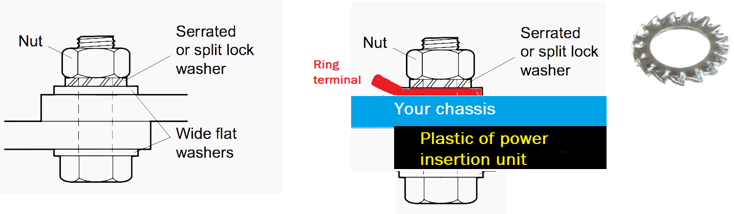
- The protective ground pin wire should be attached to a ring terminal which is then attached to one of the screws (see image below).
2. Install the Ethernet plugs
- Insert the Ethernet plugs into the matching cutouts on the back of the enclosure.
- Tighten the plastic bolt to fasten the plugs.
3. Install the banana plugs
- Thread the wire and plug through the appropriate hole cutout in the back panel. Then thread the plastic mounting cap followed by the two nuts down the wire to tighten the plug.
4. Install the Fischer connector
- Thread the wires and the connector through the Fischer connector hole cutout.
- Thread the wires through the Fischer nut and tighten the Fischer connector to the back panel.
Inside the enclosure
Placement of the PCB and microcontroller
The PCB and Microcontroller should be placed inside the enclosure. The exact placement can be customized, however the screw terminals of the PCB should face the front panel if it is intended to drive the switches inserted in the front panel, or the Fischer connector if it is intended to drive external switches connected through the Fischer connector.
If using adhesive bases for the mounting of PCB and microcontroller, it is recommended to screw the bases to the component before removing the protective paper from the adhesive base. Once the suitable location for the component is determined, remove the protective paper from the bases and press them into place. Note that the adhesive is strong, so the component is hard to remove or relocate once it has been attached.
Connecting the components
Connecting the Power Entry to the EML15US09-S converter
- Connect the
Fpin on the power entry toACLon the converter. - Connect the
Bpin on the power entry toACNon the converter.
Connecting the Arduino to the converter
- Strip two jumper wires such that they both have one male end and one bare end.
- You may have to ben the male end into an L end in order to be able to close the enclosure.
- Connect
+Vofrom the converter to theVinpin on the Arduino. - Connect
-Vofrom the converter to anyGNDpin on the Arduino (preferable the one adjacent toVin).
Connecting the Arduino to the distribution board PCB
- Connect a
5Vpin and aGNDpin from the Arduino toPWR_L1on the PCB. The PCB does not have reverse current protection. It is therefore important that you connect these correctly. If there are no markings to distinguish between positive and GND on the PCB, you can check which of thePWR_L1pins has a trace on the underside of the PCB. That is the positive pin.
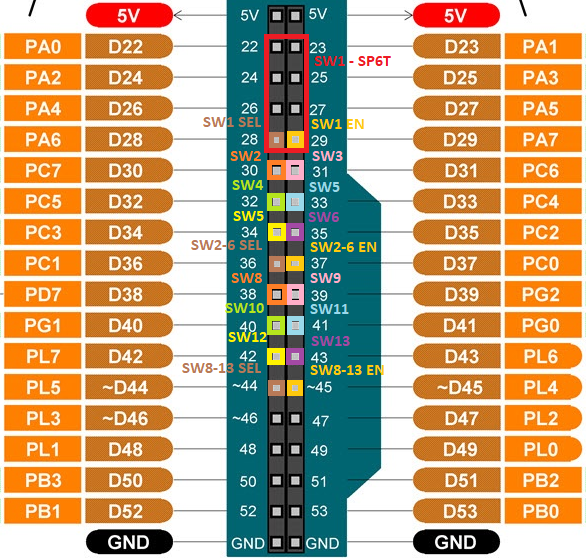
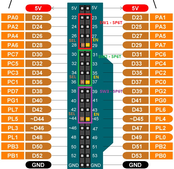
The connection between Arduino and the PCB is dependent on the pin configuration you are using, which is defined in the .ino firmware file. If you are using one of our preconfigured Switch configurations, you can follow the schematic below to determine which pins should be connected on the PCB:
3 SP6T configuration
1 SP6T + 12 SPDT configuration