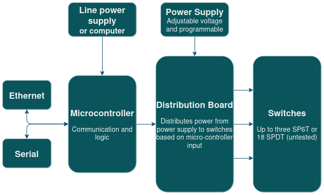
The 202Q Switch Matrix is a device for digital control of multiple radio-frequency microwave latching switches, both at room- and cryogenic temperatures. It is designed for a 1-unit (1U) size 15-inch rack enclosure, and allows for the fast and tunable control, using Ethernet or Serial communication. A diagrammatic overview of the Switch Matrix can be seen below.
The Switch Matrix is designed and tested for Radiall R591763600 SP6T switches. The enclosure is designed to house one SP6T switch and 12 SPDT switches. It also includes a Fischer connector in the back panel to allow for control of external switches. It should be noted that the Power Supply is external and not integrated in the enclosure itself.
Operating Principle
The main components of the Switch Matrix include a microcontroller with Ethernet support (realized with an Arduino Mega 2560 Rev3 with an Arduino Ethernet Shield 2) as well as a custom PCB which we call the distribution board. The distribution board distributes variable-voltage DC pulses to the connected switches based on input from the microcontroller, by routing the power from the external power supply. The current flow direction of the pulses can be inverted to alternate between latching and unlatching the switches, without requiring additional connections to the switch. The voltage of the applied pulses is determined by the external power supply.
The distribution board is designed to drive 3 SP6T switches, 18 SPDT switches, or combinations thereof (for example 1 SP6T switch and 12 SPDT switches). The microcontroller is capable of controlling up to 2 distribution boards simultaneously, allowing the Switch Matrix to drive up to 6 SP6T switches or 36 SPDT switches simultaneously (or a combination thereof).
Design
The distribution board was designed in KiCad, and the relevant design files, including a Bill of Materials for the PCB, can be found in hardware/distribution board. The full device design was designed in Autodesk Inventor, and the relevant design files can be found in hardware/enclosure.
Assembly
If assembling the Switch Matrix yourself, the enclosure needs to machined to include the correct cutouts and the distribution board PCBs have to be manufactured. Several components also require soldering. BOM.xlsx lists all required components in order to assemble the switch. enclosure.stp is a STEP-file which defines the cutouts for the enclosure. With all the components sourced, you can assemble the device by following the Assembly Instructions.
Terms of Use
This design, including both hardware and software (including firmware) is made available under the CERN Open Hardware License Version 2 - Strongly Reciprocal.